
Linear motion systems lie at the heart of modern precision machinery, automation equipment, semiconductor manufacturing, medical instruments, and high‑end metrology tools. Among the many guidance technologies available today, cross‑roller linear guideways have carved out an irreplaceable niche in ultra‑precision motion scenarios. Their distinguishing feature is a unique crossed arrangement of cylindrical rollers, which sets them apart from ball‑type guides that rely on spherical rolling elements. By optimizing force distribution, contact area, and load‑bearing performance, cross‑roller guides achieve a rare combination of high rigidity, extreme precision, low friction, and a compact footprint. This article takes a close look at cross‑roller linear guideways from multiple angles—basic structure, working principle, core strengths, performance parameters, classification, typical applications, installation and maintenance, comparisons with other linear guides, and future development trends. The goal is to offer a systematic technical reference for engineering practitioners, machine designers, and industrial researchers.
Introduction to Linear Guide Technology and the Emergence of Cross‑Roller Guides
In production machinery and precision transmission systems, linear guideways perform the critical job of supporting and guiding moving elements along a defined linear trajectory. The performance of these guides directly shapes positioning accuracy, motion smoothness, repeatability, service life, and operating noise. As high‑end manufacturing—from precision automation and aerospace to optoelectronics and semiconductors—continues to push performance boundaries, conventional sliding guides and ordinary ball‑type rolling guides are increasingly falling short of the ultra‑precision and high‑stiffness demands that emerging applications impose.
Sliding linear guides work through direct surface contact between the rail and slider. They offer high rigidity, but at the cost of large frictional resistance, noticeable wear, and poor motion smoothness. Micro‑feeding and precise positioning are difficult to achieve with sliding contacts, making these guides unsuitable for precision and ultra‑precision machines. Ball linear guides, on the other hand, use steel balls as rolling elements. They reduce friction considerably and can reach decent positioning accuracy, yet their point‑contact geometry between balls and raceways limits load capacity, rigidity, impact resistance, and vibration damping.
Cross‑roller linear guideways were developed to break through these very limitations. By replacing spherical balls with cylindrical rollers and arranging them crosswise at a fixed angle—typically 90 degrees—these guides convert point contact into line contact. The larger contact area raises rigidity and load capacity significantly, while still preserving the low rolling friction and high motion accuracy that precision systems demand. Since their commercialization, cross‑roller guides have become indispensable in high‑precision fields where ball‑type guides struggle to perform, establishing themselves as one of the most vital precision motion components in modern advanced manufacturing.
Basic Structure and Composition of Cross‑Roller Linear Guideways
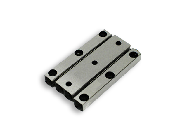
A complete cross‑roller linear guideway system is built around five core elements: the guide rail, the slider, the cross‑roller assembly, the roller retainer, and end‑stop components. Each part is designed and manufactured to exacting standards to safeguard overall precision and stability.
Guide Rail
The guide rail acts as the fixed foundation of the assembly. It is usually made from high‑carbon chromium bearing steel or stainless steel selected for high hardness, wear resistance, and dimensional stability. After precision grinding and heat treatment (quenching and tempering), the surface hardness reaches HRC 60–62, which guarantees long‑term resistance to wear under repeated rolling contact. The inner surface of the rail features two symmetrical sets of V‑shaped raceways machined at a precise inclination, matching the crossed‑roller layout. The quality of raceway grinding directly determines the straightness, parallelism, and flatness of the entire guideway system—it is the single most critical manufacturing step for final motion accuracy.
Slider
The slider is the moving counterpart that mates with the guide rail, carrying the load and delivering the motion output. It too is made from high‑precision alloy steel or stainless steel, with matching V‑shaped raceways on its inner faces. Mounting holes on the slider allow connection to external moving parts such as stages, tool heads, and fixtures. The slider’s design is compact yet structurally stiff, enabling it to resist bending and torsional deformation under heavy and impact loads.
Cross‑Roller Assembly
Instead of balls, cross‑roller guides use cylindrical rollers as rolling elements. These rollers are high‑precision cylinders with tightly controlled dimensional tolerances and nanometer‑level surface finishes obtained through fine grinding. The defining feature is their cross‑arrangement: adjacent rollers are placed alternately at a 90‑degree angle. Some rollers carry horizontal loads, while the adjacent ones carry vertical loads. This layout allows the guideway to simultaneously support loads from multiple directions—radial, reverse radial, horizontal, and vertical—providing genuine multi‑directional load capacity.
The contact between rollers and raceways is line contact, rather than the point contact of ball guides. Under a given load, line contact distributes pressure far more evenly, reduces local stress concentrations, and improves both the load‑bearing limit and overall rigidity. Vibration damping and impact resistance are also markedly better.
Roller Retainer
The roller retainer is a crucial auxiliary component that keeps rollers properly spaced and prevents them from falling out or skewing during movement. It is typically made of high‑strength engineering plastic or lightweight metal, with evenly spaced pockets that match the roller dimensions. The retainer maintains uniform roller spacing, avoids mutual friction and collision between rollers, stabilizes the rolling motion, and effectively reduces operating noise and wear. It also restricts axial displacement of the rollers, preserving the long‑term stability of the crossed arrangement.
End‑Stop and Dust‑Proof Components
End‑stop blocks are mounted at both ends of the guide rail to limit the slider’s stroke and prevent derailing or roller ejection during over‑travel. Dust‑proof strips and oil‑seal elements fitted on the slider ends keep out dust, metal chips, cutting fluids, and other contaminants, protecting the rolling contact area from abnormal wear and extending service life.
Working Principle of Cross‑Roller Linear Guideways
At its core, a cross‑roller guide converts sliding friction into rolling friction through the action of crossed cylindrical rollers traveling between the guide rail and slider. When an external force drives the slider along the rail, the cylindrical rollers roll continuously within the V‑shaped raceways. Because of the 90‑degree cross layout, half of the rollers handle upward and downward vertical loads, while the other half handle left‑right horizontal loads. As the slider moves back and forth, the rollers circulate cyclically between the rail and slider raceways under the retainer’s constraint.
Sliding contacts exhibit a high coefficient of friction; in contrast, the rolling friction coefficient of cross‑roller guides is extremely low, typically between 0.001 and 0.003. This is far lower than that of sliding guides and marginally lower than that of ordinary ball guides. The line‑contact geometry ensures that stress is spread uniformly across the roller surfaces, avoiding the local stress peaks and plastic deformation that point contact can cause. Under heavy loads and impact conditions, the rollers maintain stable contact without crushing or indenting the raceways.
In ultra‑precision micro‑feed operations, cross‑roller guides deliver smooth motion with no stick‑slip (crawling). Stick‑slip—unstable intermittent motion caused by an unfavorable difference between static and dynamic friction coefficients—is a common headache with sliding guides and can affect some ball guides as well. The low‑friction, high‑stiffness architecture of cross‑roller guides guarantees stable motion even at extremely low speeds, satisfying the needs of nanometer‑level positioning.
Core Advantages of Cross‑Roller Linear Guideways
When placed alongside sliding guides, ball linear guides, and dovetail guides, cross‑roller linear guideways stand out in precision, rigidity, load capacity, motion smoothness, and structural compactness. The key advantages can be summarized as follows:
Ultra‑High Motion Precision and Repeatability
Cross‑roller guides rely on precision‑ground raceways and high‑accuracy cylindrical rollers manufactured to tight tolerances. Straightness errors can be kept within micrometers, and repeatability can reach 0.1–1 μm, with even nanometer‑level performance achievable in customized ultra‑precision versions. The crossed‑roller design effectively eliminates motion clearance; by applying a preload to the rollers, zero‑clearance operation becomes possible. This avoids the positioning errors that arise from clearance reversal during forward‑and‑reverse motion. For precision measuring instruments, optical inspection systems, and semiconductor lithography equipment, these capabilities make cross‑roller guides the preferred solution.
High Rigidity and Multi‑Directional Load Capacity
Line contact between rollers and raceways creates a contact area that is dozens of times larger than the point contact of ball guides. For a given external load, contact stress drops dramatically, giving cross‑roller guides exceptionally high static and dynamic rigidity and strong resistance to deformation. The 90‑degree crossed arrangement allows simultaneous support of vertical, horizontal, radial, reverse‑radial, and moment loads—accommodating the complex force conditions found in multi‑axis equipment. In heavy‑duty precision machinery, cross‑roller guides can hold tight accuracy under substantial loads, something ball‑type guides simply cannot match.
Low Friction, Stable Motion, and No Stick‑Slip
The rolling friction coefficient of cross‑roller guides is very low, and the difference between static and dynamic friction is minimal. Even at ultra‑low speeds below 1 mm/min, the slider moves in a smooth, continuous line without stick‑slip, jitter, or intermittent vibration. This behavior is essential for precision grinders, micro‑positioning stages, and medical surgical robots that demand flawless motion stability. Low friction also means the required driving force is small, which cuts energy consumption and reduces motor power requirements, streamlining the overall drive system design.
Compact and Space‑Saving Design
Cross‑roller guideways have a flat, compact overall structure. Their cross‑sectional size is smaller and their weight lower than ball guides of equivalent load capacity. They can be installed in narrow, space‑constrained equipment such as miniature automation modules, precision optical instruments, and micro‑machining setups. The simple rail‑and‑slider layout also simplifies multi‑axis stacking, making it straightforward to build high‑precision motion platforms like X‑Y‑Z three‑axis stages.
Strong Impact Resistance and Vibration Damping
The line‑contact design gives cross‑roller guides excellent impact resistance. When an instantaneous impact load strikes, the rollers distribute the force evenly, protecting the raceways from localized damage. At the same time, the dense roller arrangement forms an effective vibration‑damping system that absorbs high‑frequency vibrations generated during operation. This improves the stability of precision machining and measurement processes and reduces noise caused by mechanical vibration.
Long Service Life and Low Maintenance
Hardened raceways and precision‑ground rollers offer outstanding wear resistance. Under appropriate preload and normal lubrication conditions, cross‑roller guides deliver a long operational life. Because the rolling motion is stable, wear progresses evenly, and accuracy degrades very slowly. Routine lubrication and dust‑proof maintenance are usually enough to keep the system running reliably for years, greatly reducing maintenance costs and equipment downtime.
Main Classifications of Cross‑Roller Linear Guideways
Cross‑roller linear guideways can be categorized by structural form, preload method, installation style, and material selection to suit a wide range of industrial environments:
Classification by Structural Form
Integrated cross‑roller guides:** The rail and slider form a single compact unit with high overall precision, ideal for miniature precision devices.
Split cross‑roller guides:** Separate rails and sliders allow flexible stroke adjustment, suited to long‑stroke linear motion systems.
Cage‑type cross‑roller guides:** These incorporate an independent roller retainer and can realize long‑stroke continuous motion, making them popular in automation platforms.
Classification by Preload Mode
Preloading is a critical technique for eliminating clearance and boosting rigidity. Cross‑roller guides are available in zero‑clearance, light‑preload, medium‑preload, and heavy‑preload versions. Light preloads suit light‑load, high‑speed applications; medium preloads fit general precision automation equipment; heavy preloads serve heavy‑duty, high‑stiffness precision machinery.
Classification by Material
Bearing steel cross‑roller guides:** High hardness, strong wear resistance, and cost‑effectiveness make these the workhorse for most industrial precision applications.
Stainless steel cross‑roller guides:** Corrosion‑resistant and rust‑proof, these are specified for medical devices, food machinery, semiconductor cleanrooms, and humid or corrosive environments.
Classification by Stroke and Precision Grade
Guides are also grouped by stroke length—micro‑stroke miniature guides, short‑stroke precision guides, and long‑stroke heavy‑duty guides—and by positioning accuracy, ranging from general precision and high precision to ultra‑precision and nanometer‑precision grades.
Typical Industrial Applications of Cross‑Roller Linear Guideways
Drawing on their high precision, high rigidity, and low friction, cross‑roller linear guideways have found their way into numerous high‑end manufacturing fields, spanning precision machinery, optoelectronics and semiconductors, medical equipment, aerospace, and automation.
Semiconductor and Electronics Manufacturing
Semiconductor processes—wafer dicing, chip packaging, circuit board testing, and lithography—demand nanometer‑level positioning accuracy and ultra‑stable motion. Cross‑roller guides are used in wafer transfer stages, die bonders, and precision inspection equipment, where they ensure stable handling of micro‑electronic components and prevent motion‑induced processing errors. Stainless steel, anti‑corrosion cross‑roller guides are widely applied in dust‑free semiconductor fabs to meet strict cleanroom requirements.
Precision Measuring Instruments and Optical Equipment
High‑precision metrology instruments such as coordinate measuring machines, optical projectors, laser interferometers, and microscope inspection systems depend on cross‑roller guides for linear movement. The ultra‑high straightness and repeatability of these guides guarantee accurate data acquisition. In optical focusing platforms and laser processing equipment, cross‑roller guides provide stable micro‑feed motion for optical components, directly improving processing quality and image clarity.
Medical Devices and Biomedical Equipment
Medical equipment imposes strict demands on precision, stability, and hygiene. Cross‑roller guides appear in surgical robots, CT scanning systems, precision medical analyzers, and dental processing machines. Stainless steel variants offer rust resistance and easy‑to‑clean surfaces that meet medical sanitation standards, while the low‑noise, smooth motion enhances both the safety and stability of medical procedures.
Precision Machine Tools and Grinding Equipment
Ultra‑precision grinding machines, tool grinders, and micro‑cutting equipment must bear heavy loads while executing high‑precision micro‑feeds. Heavy‑preload cross‑roller guides maintain high rigidity under aggressive cutting forces, safeguarding the dimensional accuracy and surface finish of precision parts. They are also employed in precision fixture positioning tables on CNC machine tools.
Automation Equipment and Precision Robots
In automated production lines, multi‑axis stages, precision pick‑and‑place robots, and assembly mechanisms, cross‑roller guides enable high‑speed, high‑precision reciprocating motion. Their compact structure saves installation space, while their multi‑directional load capacity adapts to complex multi‑axis movements, boosting both the level of automation and the efficiency of production lines.
Aerospace and Precision Instrumentation
The processing of aerospace components, testing of satellite parts, and inertial navigation equipment all require ultra‑high precision and reliability. Cross‑roller guides deliver stable performance under extreme temperatures and vibration, making them a trusted choice for aerospace test platforms and precision instrument transmission systems.
Installation, Lubrication, and Maintenance of Cross‑Roller Guideways
Getting the best out of cross‑roller linear guideways calls for disciplined installation, proper lubrication, and consistent maintenance.
Installation Requirements
The mounting base must offer high flatness and rigidity; an uneven base will distort the guide rail and erode precision. The rail should be leveled and secured using torque‑controlled bolts to achieve uniform clamping force. When two parallel rails are used, their parallelism must be strictly controlled. Throughout installation, it is important to avoid impacts or knocks on the rollers and raceways that could cause surface damage.
Lubrication Management
Cross‑roller guides need reliable, long‑term lubrication. Grease lubrication is standard for general‑speed equipment, while oil lubrication suits high‑speed, heavy‑duty scenarios. The lubricant forms a thin film between rollers and raceways, reducing friction and wear and preventing corrosion. Lubricant should be replenished regularly according to operating frequency and environmental conditions, and dust‑proof elements should be cleaned to avoid lubricant contamination.
Daily Maintenance
Periodic checks of slider travel smoothness, operating noise, and positioning accuracy are recommended. Worn dust‑proof strips and oil seals should be replaced in a timely manner. Overload and impact operation beyond the rated capacity must be avoided. For equipment that will be shut down for an extended period, applying anti‑rust grease prevents roller corrosion. Disciplined maintenance can extend service life by more than 30% and preserve long‑term precision stability.
Comparison Between Cross‑Roller Guides and Other Common Linear Guides
To better illustrate where cross‑roller guides excel, a multi‑dimensional comparison with sliding guides, ball linear guides, and dovetail guides is useful:
- Cross‑roller guides outperform ball guides, which in turn surpass dovetail guides and sliding guides. Cross‑roller systems achieve nanometer‑level accuracy, whereas sliding guides are limited to low‑precision tasks.
- Cross‑roller guides take the lead, followed by sliding guides, dovetail guides, and ball guides. Line contact inherently delivers higher rigidity than point contact.
- Cross‑roller guides and ball guides are comparably low, dovetail guides are higher, and sliding guides the highest. Both rolling‑element types keep friction minimal.
- Cross‑roller guides can carry heavier loads than ball guides because line contact handles force more effectively than point contact.
- Cross‑roller guides show no stick‑slip at low speeds; ball guides may exhibit slight stick‑slip, while sliding guides suffer from obvious stick‑slip.
- Cross‑roller guides are the most compact, making them especially suitable for tight‑space installations.
In practice, ball guides fit high‑speed, medium‑precision scenarios, sliding guides serve low‑precision heavy‑duty equipment, and cross‑roller guides are the go‑to choice for ultra‑precision, high‑rigidity, and micro‑motion applications.
Conclusion
Thanks to their unique crossed‑roller layout, line‑contact rolling mechanism, and a compelling blend of ultra‑high precision, high rigidity, low friction, multi‑directional load capacity, and compact construction, cross‑roller linear guideways have secured their place as core building blocks in modern ultra‑precision manufacturing. From fundamental structure and operating principle to performance advantages, classification, industrial applications, and maintenance practices, these guides show an irreplaceable superiority over traditional linear motion components in demanding high‑end scenarios.
With the rapid growth of the semiconductor industry, intelligent manufacturing, medical equipment, and aerospace technology, the market demand for cross‑roller linear guideways continues to expand. Ongoing innovation in precision machining, material science, and intelligent monitoring will further broaden their application scope, providing ever more reliable motion support for high‑end manufacturing equipment and driving progress across the global precision machinery industry. For machine designers and industrial engineers, thoughtful selection and application of cross‑roller linear guideways is a practical and impactful way to boost equipment precision, stability, and overall performance—making a tangible difference to the advancement of high‑end manufacturing.